
35 mm alignment strip
Vlads Test Target has addition to the family -
“35 mm alignment strip”
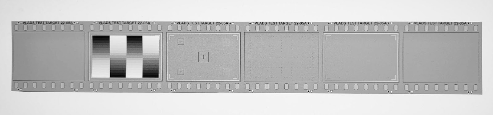
"35 mm alignment strip” is the high precision test target executed via high-fidelity laser printing on specialty Agfa-Gevaert photographic film. Because of how it's made, the image elements are geometrically perfect - lines are straight and parallel to each other, the fine raster is very uniform and is distortion-free.
IMG_20221225_153412141.jpg
What does that bring to the field of camera scanning?
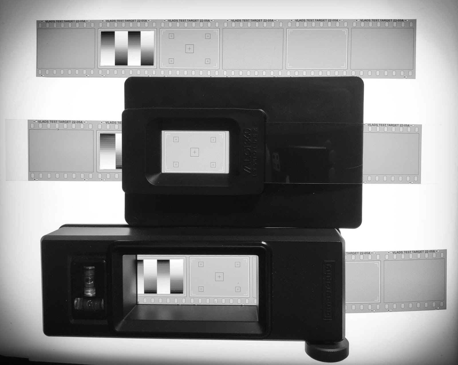
The target geometrically resembles a 35 mm film strip (type 135). All markings on film are per the spec, including the 24x36 mm frame which corresponds to the typical film camera gate. While positioning the strip in a scanning film holder, user can observe exactly how the actual negative will fit in the film holder and any parts which might be exposed or obscured.
IMG_20221225_154220492.jpg
The target also contains marking 23x35 mm depicting how a typical mount would mask parts of the frame to remove the edge imperfections.

35mmstrip-ab-02-legend3.jpg
Overall strip marking allows the user to set the scanning rig exactly the way they want the frame to be captured.
The test strip has 50% raster which covers the strip entirely.
20221223-2022_12_23_0608-2.jpg
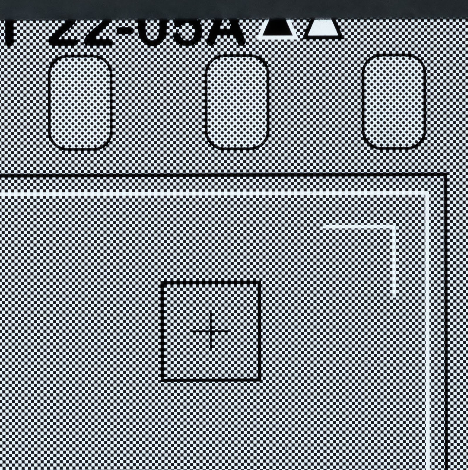
The raster contains transparent and opaque squares with extremely high edge contrast (acutance). The human eye perceives the grid as a uniform gray color, but the camera easily resolves those square elements. The shape and sharpness of the squares when observed on a computer screen provides the crucial information about the quality of scanning setup. Users can judge immediately if the captured image is sharp, if sharpness varies between center and all or some frame edges.
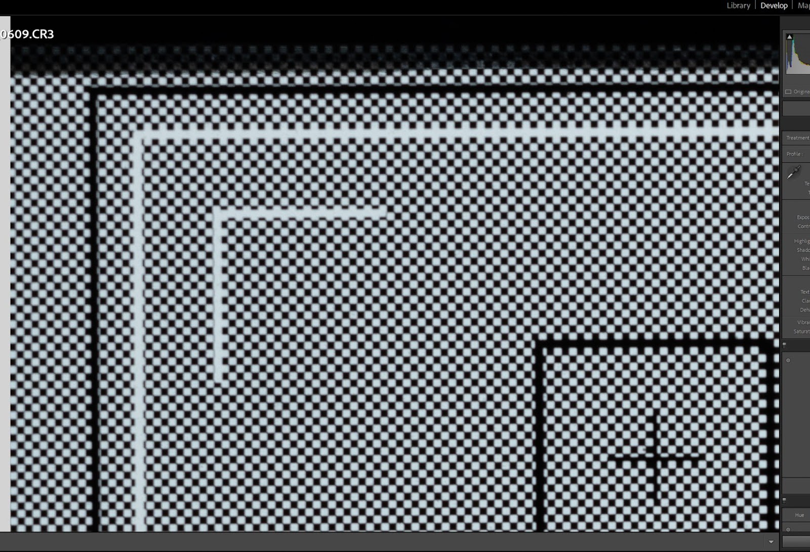
Here is how the image may look like if the corner is out of focus.
2022-12-23 (2).jpg
There is also a simple procedure which allows to check the evenness of the illumination and presence of the light fall-off.
How to use the strip
Place the strip in the film holder and center it properly based on markings on the strip and the holder's opening.
Turn on the camera and observe the frame. Use focus peaking feature (if available) to focus the lens. Move the camera up and down and correct focus to capture the desired part of the image. The marking allows users to clearly see what parts of the image will be captured and whether the film holder is oriented properly.
Make the capture. The tethered capture is highly recommended. First, that helps to avoid camera disturbance and shake, second, that speeds up picture transfer to the computer.
Use any available software to examine picture at 100% magnification on a computer screen. Start with reviewing the center.
If the center is not sharp and clear, repeat focusing and adjust exposure until the center looks perfect.
If the center looks like it is a bit smudged, that means the shutter speed is not fast enough to "freeze" the image or the rig itself is prone to external vibration. Fix the issue with vibration and proceed further.
Once the grid is sharp and has proper contrast, start reviewing the frame sides and corners.
If you observe that one side or corner is noticeably less sharp than the other - the misalignment between camera sensor and test target film plane is most likely culprit. Adjust camera and film holder positions until all corners and edges are similarly sharp.
If corners and edges are similarly sharp, but not as sharp as the center of the image, the most likely issue is lens deficiency - try to shoot at different aperture openings to see if this helps. The majority of lenses we use are at their best at F/8 or +-1 stop.
If the problem persists - get another lens.
Finally, once the captured image is uniformly sharp across the frame, you have completed the most complex and labor intensive part of scanning rig tuning. Now you may replace the test target with your own film and you are ready to start scanning.
Advanced use: analyze the uniformity of back illumination
The quite common issue folks have to deal with, is unevenness of light used to illuminate the original to be scanned. That issue is separate from the quality of the light color-wise. The core idea is the same as the technique invented 130 years ago to reproduce photographs in print media. Max Levy patented the use of halftone screens to rasterize the continuous-tone image into the grid of the dots of the varying size. We will do the same by employing Levels tools in Photoshop or Lightroom and will reveal which individual squares in the grid have different brightness and /or sharpness.
The image of the test target which consists of pure raster is captured as usual. Then, in the software like Lightroom the curves get applied to the image to increase contrast almost to insanity.

2022-12-23 (4).jpg

2022-12-23 (4)-2.jpg
Once the highlights and midtones get eliminated, the grid elements with brightness differences become easily observable. In the brightest areas the black grid elements get surrounded by brighter elements which will bleed light into darker squares. The result is black elements become relatively smaller and reveal areas with higher brightness. The operator now has to adjust backlight to even out intensity across the frame. Uneven illumination is the most common cause of weird color casts and funny colors when negative is inverted and light was not uniform across the frame. The holder edges do affect the areas of film in close proximity (via the shadows and light dispersion) so one has to pay attention to those effects too and take appropriate countermeasures.
F.A.Q.
Q. Do I need both a "35 alignment strip" and 35 mm test target with USAF 1951 patterns or can I get away with just one target?
A. You may want Vlads Test Targets with USAF1951 patterns if you want to know for certain what resolution in lines per mm your scanning rigs allows you. You may want to quantify the resolution differences between center and corners or you may want to compare different lenses. If you don’t really care about lp/mm numbers and trust your eyes while reviewing test images - you will be perfectly fine with the alignment strip. Besides, strip allows for certain functionality - like analysis of uniformity of back illumination.
Q. The alignment strip does not have actual perforations, how does that affect the film holders with drives for 35 mm film?
A. This is true -there is no real perforations. The strips have been tested fine with VALOI Advancer and Digitaliza + drive. I cannot say which holders actually need perforations to advance film thru.
Q. What about Type 120 and 4x5 Vlads Test Targets? Do they have the features described above?
A. Yes, they do! Type 120 and 4x5 Vlads Test Targets are made using the same laser technology and media. They have the raster covering almost all areas between USAF 1951 targets so that makes possible the application of the technique described above.


Comments
Post a Comment