
Vibration-Proof Scanning Setup: Is Yours Up to the Task?
.png)
Blurring the edges
Certainly, let's start from the basics and define what is meant by "blur". Blurring on a camera occurs as a result of movement of the camera, subject, or both. Motion blur specifically refers to the streaking or smearing seen in the image due to this movement [1].On the other hand, vibration blur is specific to when the camera oscillates around a mounting point, causing a loss of sharpness as elements overlap and micro-contrast decreases. In digital images, this can be seen as the smallest details, such as object edges, being spread across multiple pixels rather than producing a contrast between neighboring pixels. Let's run some numbers to better understand the effects of these types of blur.
Given these parameters, let's examine a typical camera scanning setup. The camera and lens are suspended on an arm attached to a long, thin copy stand column. Despite what manufacturers claim, the camera can easily be disturbed or moved by 5 microns in either direction. To put this in perspective, human hair diameter ranges from 50 to 90 microns, so 5 microns is a very small value and would not be a concern if not for the 1:1 reproduction involved in camera scanning.

Now we need an object that's about 5.5 microns in size to be test captured. Luckily, many members in our group have "Vlads Test Target" with a USAF 1951 resolution power chart.

That would be wonderful, unless there were no unpleasant limitations on the camera side that hinder this plan. Theoretically, a camera with a sensor pixel pitch of 5.5 microns should be able to resolve 90.9 line pairs per millimeter, but this is not the case in practice.
Even before addressing the lens, it's important to note that in reality, the high resolution limit would likely be approximately 40% lower than the values listed in the chart above.
Unfortunately, this means that cameras with a pixel pitch of around 5.5 microns, like those typically used by amateur photographers, will likely only achieve a resolution of 64.5 line pairs per millimeter, far lower than the theoretical maximum of 90.9.
When considering the lens, the situation becomes even less certain. The combined resolution of the sensor and lens will always be lower than the resolution of each individual component. Assuming that we have a high-quality lens, the overall resolution will only decrease slightly.
Based on these factors, it's clear that a camera with a sensor and lens as described will realistically be unable to resolve better than Group 0 Element 2 on the Vlads Test Target. This explains why the I saw only slight improvement when using APO-Rodagon-D 2x 75 mm vs Sigma 70 mm Macro Art on my Canon EOS R camera, despite seeing other benefits like a flatter field of view for Rodagon which allowed me to shoot at f/6.3 instead of f/9 for Sigma .
To determine if our scanning rig is stable enough to capture objects with a thickness of 8 microns, we need to perform a simple test. We start by placing a strip of the "Vlads Test Target'' with the USAF 1951 resolution power chart in the film holder and taking a series of photos. Keeping the aperture constant, we vary the light intensity, and so shutter speed changes accordingly. I simply took advantage of having CMY wheels and changed filtration from 0Y 0M 0C to 200Y 200M 200C in 10Y 10M 10 C steps. That caused the shutter speed to change from 1/400 to 1/13 sec. It is important to avoid adjusting the aperture, as this may affect the sharpness of the image. We want any changes in the appearance of the smallest elements of the chart to be a result of exposure time and possibly the vibrations rather than anything else. The goal is to capture images with as long an exposure as possible before motion blur becomes apparent, and as short an exposure as possible before motion blur is no longer detectable.
To determine the best shutter speed for scanning, all you need to do is compare the smallest elements on the "Vlads Test Target" in a sequence of shots while observing how they are merged, smudged, or separated. Lightroom's shot comparison feature with scale synchronization makes this process very simple. Conduct this comparison at 100% magnification in a dimly lit room. It's recommended to avoid using 200% magnification as it doesn't provide any additional information (IMHO). By comparing the shots, you will be able to determine with confidence the longest shutter speed you can use without any motion blur. Note that this process should be performed while paying attention to changes in the sharpness of the smallest resolvable element on the target. I tracked the changes in Group 0 Elements 2 and 3.
The results are provided in this short video which shows sharpness variations while shutter speed changes from 1/400 to 1/13 of sec and back. The aperture was constant at f/6.3.
In my case, I was disappointed to find out that my scanning rig could only handle a shutter speed of no longer than 1/160 sec. That’s pretty demanding value from the light intensity point of view. Now the advantage of the Rodagon lens comes into full view as it helped me gain 2 full stops compared to the Sigma 70 mm Macro Art lens.
The sources of vibrations can be multiple from shutter shock to vibrations induced by the street traffic.
In essence, the described method provides a way for you to evaluate the achievable resolution of your camera when scanning. This exercise allowed me to see the importance of lens selection, specifically choosing a lens with a wider aperture.
It’s important to note, that on one hand the most likely limit on overall scan resolution comes from the sensor pixel pitch, on the other hand wider lens aperture allows shorter exposure times and helps to deal with all sorts of camera vibrations which strongly influence image quality at the given reproduction range of 1:1.
In conclusion let me make couple of notes:
1. The use of flash or studio strobes for back illumination during scanning is not discussed here, as their short bursts of light make them the preferred choice for those with a less stable scanning rig. However, most people opt for continuous lights such as LED lights or halogen lights, which are easier to handle but may not produce enough intensity.
3. One may ask why we are talking about camera shake if we can use an electronic shutter which is completely motionless. For one thing, I discovered that even having a halogen lamp as the light source (and this lamp has very significant thermal inertia) the shots were uneven and looked like some sort of wave was superimposed on them. I heard similar complaints from other folks so the situation is not unique. Besides, conventional sources of vibration abound in almost any building. Need proof? Turn on live view, set magnification to x10 and peek at the viewfinder. The image is never steady, you will observe vibrations all the time even if you hold your breath.
In conventional photography, we typically deal with reproduction ratios from 1:20 to 1:10…0, so the displacement of the image is scaled down by the same factor. However, in macro photography or camera scanning, the displacement of the image is roughly equivalent to the displacement of the original.
For the fistful of micrometers
To avoid even slight motion blur in a camera scanning scenario, the camera’s displacement during exposure must not exceed a certain small critical value. This displacement can be estimated by calculating the distance between pixels, also known as pixel pitch. This is done by dividing the size of the sensor in millimeters by the image size in pixels. For example, the pixel pitch for a Canon EOS R camera is 5.4 microns, while for Sony high-resolution cameras it may be 3.7 microns. These values can easily be found with a simple Google search.
So in camera scanning, with the typical reproduction ratio of 1:1 or 1:1.6, if the camera is displaced by even 5.4 microns during capture, it will result in image blurring and will reduce the resolution by 50% on the spot.
Freezing the action
Now, let's consider the shutter speed during capture. It's a well-known fact that the shorter the exposure time, the less the blur. This means that regardless of the reason for the image moving across the sensor (or film), the smaller the distance it moves, the sharper the object becomes - until it "freezes" when the distance it moves is smaller than the pixel pitch or circle of confusion for film.
Given these parameters, let's examine a typical camera scanning setup. The camera and lens are suspended on an arm attached to a long, thin copy stand column. Despite what manufacturers claim, the camera can easily be disturbed or moved by 5 microns in either direction. To put this in perspective, human hair diameter ranges from 50 to 90 microns, so 5 microns is a very small value and would not be a concern if not for the 1:1 reproduction involved in camera scanning.
So let's see if those estimates can be applied to the real scanning rig based on Beseler Dual-Mode Slide Duplicator, Canon EOS R, APO Rodagon D 2X, and VALOI film folder which I fashioned on top of Beseler negative holder. The beauty of this setup is that it has the option to use either a 250W halogen lamp or build-in flash. Dichroic filters can be engaged just like on any color lamp house.
Now we need an object that's about 5.5 microns in size to be test captured. Luckily, many members in our group have "Vlads Test Target" with a USAF 1951 resolution power chart.
Element 5 in Group 0 has a resolution of 87 line pairs per millimeter, meaning that each pair takes up 11.5 microns of space on the actual Adox CMS film used to make the targets. The thickness of each line in the pair is 5.5 microns, which is close to what we want to observe in our capture and determine if it gets blurred during capture in a scanning rig at different shutter speeds.
 |
| This photograph was taken in optical microscope at 200x magnification. The strokes in red oval are approximately 5.5 micrometers wide. |
 |
Even before addressing the lens, it's important to note that in reality, the high resolution limit would likely be approximately 40% lower than the values listed in the chart above.
Unfortunately, this means that cameras with a pixel pitch of around 5.5 microns, like those typically used by amateur photographers, will likely only achieve a resolution of 64.5 line pairs per millimeter, far lower than the theoretical maximum of 90.9.
When considering the lens, the situation becomes even less certain. The combined resolution of the sensor and lens will always be lower than the resolution of each individual component. Assuming that we have a high-quality lens, the overall resolution will only decrease slightly.
Based on these factors, it's clear that a camera with a sensor and lens as described will realistically be unable to resolve better than Group 0 Element 2 on the Vlads Test Target. This explains why the I saw only slight improvement when using APO-Rodagon-D 2x 75 mm vs Sigma 70 mm Macro Art on my Canon EOS R camera, despite seeing other benefits like a flatter field of view for Rodagon which allowed me to shoot at f/6.3 instead of f/9 for Sigma .
To determine if our scanning rig is stable enough to capture objects with a thickness of 8 microns, we need to perform a simple test. We start by placing a strip of the "Vlads Test Target'' with the USAF 1951 resolution power chart in the film holder and taking a series of photos. Keeping the aperture constant, we vary the light intensity, and so shutter speed changes accordingly. I simply took advantage of having CMY wheels and changed filtration from 0Y 0M 0C to 200Y 200M 200C in 10Y 10M 10 C steps. That caused the shutter speed to change from 1/400 to 1/13 sec. It is important to avoid adjusting the aperture, as this may affect the sharpness of the image. We want any changes in the appearance of the smallest elements of the chart to be a result of exposure time and possibly the vibrations rather than anything else. The goal is to capture images with as long an exposure as possible before motion blur becomes apparent, and as short an exposure as possible before motion blur is no longer detectable.
 |
| Initial shots at 1/400 and 1/250 sec shows us no differences. |
 |
| We are seeing deterioration at 1/125 sec |
 |
| At 1/13 we lost a lot of resolution. |
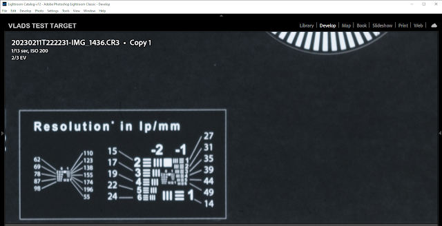 |
| We lost a lot and note we lost resolution in different degree in each direction. Horizontally we lost all the way to 31 lp/mm and vertically we lost to 49 lp/mm which tells us even the direction of the camera shake. |
To determine the best shutter speed for scanning, all you need to do is compare the smallest elements on the "Vlads Test Target" in a sequence of shots while observing how they are merged, smudged, or separated. Lightroom's shot comparison feature with scale synchronization makes this process very simple. Conduct this comparison at 100% magnification in a dimly lit room. It's recommended to avoid using 200% magnification as it doesn't provide any additional information (IMHO). By comparing the shots, you will be able to determine with confidence the longest shutter speed you can use without any motion blur. Note that this process should be performed while paying attention to changes in the sharpness of the smallest resolvable element on the target. I tracked the changes in Group 0 Elements 2 and 3.
The results are provided in this short video which shows sharpness variations while shutter speed changes from 1/400 to 1/13 of sec and back. The aperture was constant at f/6.3.
.gif) |
| GIF illustration |
Note that the only variable was the amount of light. The camera was set to Aperture priority so shutter speed got changed according to the available light. Nothing else was changed, the shutter was triggered thru the tether.
The sources of vibrations can be multiple from shutter shock to vibrations induced by the street traffic.
In essence, the described method provides a way for you to evaluate the achievable resolution of your camera when scanning. This exercise allowed me to see the importance of lens selection, specifically choosing a lens with a wider aperture.
It’s important to note, that on one hand the most likely limit on overall scan resolution comes from the sensor pixel pitch, on the other hand wider lens aperture allows shorter exposure times and helps to deal with all sorts of camera vibrations which strongly influence image quality at the given reproduction range of 1:1.
In conclusion let me make couple of notes:
1. The use of flash or studio strobes for back illumination during scanning is not discussed here, as their short bursts of light make them the preferred choice for those with a less stable scanning rig. However, most people opt for continuous lights such as LED lights or halogen lights, which are easier to handle but may not produce enough intensity.
2. It is important to note that motion blur is not always a bad thing and can sometimes enhance the final look of the picture by averaging the grain of conventional emulsions. The decision to employ motion blur should ultimately be left up to the artist.
3. One may ask why we are talking about camera shake if we can use an electronic shutter which is completely motionless. For one thing, I discovered that even having a halogen lamp as the light source (and this lamp has very significant thermal inertia) the shots were uneven and looked like some sort of wave was superimposed on them. I heard similar complaints from other folks so the situation is not unique. Besides, conventional sources of vibration abound in almost any building. Need proof? Turn on live view, set magnification to x10 and peek at the viewfinder. The image is never steady, you will observe vibrations all the time even if you hold your breath.
[1]
Disclose: the scanning ring image at the top was generated by Midjourney based on the photograph of my setup.


Comments
Post a Comment